Leyland P76 Owners 2006 |
Technical problem |

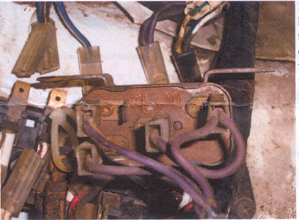
Horn Relays and wiring
A TRICKY TECH-TIP....BY DR. PHILTHY, OF COURSE!
- Recently, I had a call from a P-nut who was doing a spot of engine-bay wiring tidying-up.
- He wanted to fit a "new" original-style horn relay, and he wasn't too sure about which wire went where on the replacement relay.
- Most P-nutz will know that there are a few purple-coloured wires, which should connect to the terminals on the horn relay.
- The trick, of course, is to make sure that they are connected to the correct terminals!
- It won't hurt to review what we know about relays in general before I waffle on about how to wire up P-76 horn relays.
- A relay is an electrically operated switch, which makes the operation of various electrical equipment, more efficient, by eliminating unnecessary wiring between the power source and the equipment.
- Most relays have four terminals altogether. They are two control" or "switch" terminals, a power supply terminal ("power in"), and a power "out" terminal.
- The Lucas relays used as original equipment on P76's also have four terminals. The control or switch terminals are marked WI and W2, the "power in" terminal is marked C2, and the "power out" terminal is marked C 1.
- If you connect one of the "W" terminals to a power source, and the other "W" terminal to earth, you should hear a definite "click" as the relay solenoid operates.
- When the solenoid operates, it brings two contacts in the body of the relay together and thus connects electrically, the Cl and C2 terminals.
- In a standard, un-mongreled P-76 wiring harness, a wire, which is switched to earth to complete a circuit, is marked with a black stripe or trace.
- The light green wire, which operates the screen washers, has a black trace.
- The horn wiring circuit has a purple wire with a black trace, too. In the P76, the "switch" to operate the horns is the padded boss on the steering wheel, which completes an earth circuit when it contacts the metal hub of the steering wheel.
- This is connected to the P-76 chassis by one of the two wires in the steering column canister.
- My best guess here is that the blue/yellow wire in the canister is connected to the horn relay's earth terminal, and the blue wire in the canister provides the horn switch with a good earth connection, usually somewhere under the dash-board support panel, near the steering column support bracket.
- As mentioned above, the purple wire with the black trace is connected to the horn pad via the blue/yellow wire in the steering column canister.
- This purple/black wire should be connected to one of the "W" terminals on the base of the relay.
- There are two plain purple wires.
- They are the power supply wires.
- One of these plain purple wires should be connected to the other "w" terminal, and the other one should be connected to the C2 terminal. The purple/yellow trace wire takes the power from the relay to the horns, so it should be connected to the C I terminal.
- When all of the wires have been connected as detailed above, the horns should work.
- If they don't work, there is a fairly simple procedure to follow to identify the location of the fault.
- The first thing to check, is that the horns actually work.
- Disconnect the purple/yellow wire from the C I terminal.
- Fabricate a jumper lead from some spare wiring, and connect one end of this jumper lead to the purple/yellow wire. Touch the other end of the jumper lead to the battery positive terminal. The horns should operate.
- If the horns do not operate, try fitting one or two substitute horns, and try the test with the jumper lead again.
- If the substitute horns do not operate, test each of the original horns by connecting the jumper lead to each horn in turn.
- Touching the other end of the jumper lead to the battery positive terminal while holding the body of each horn on the negative terminal, which earths the horn direct to the battery negative terminal.
- If the horns now operate, the problem must be in the wiring loom between the relay and the horns.
- Remember that our P'S wiring harnesses are now more than thirty years old, and there is always a chance that some portion of your wiring harness has become chafed or corroded.
- Now, if you have established that the horns work, and the wiring between the relay and the horns is serviceable, but the horn pad on the steering wheel does not operate the horns, the next step is
- as follows:
- For the horns to work there must be power at the relay terminals where the plain purple wires connect.
- Check with a test lamp that there is power at both of these terminals.
- The power for the horn relay comes from the third fuse from the rear of the fuse box.
- Note that this fuse also supplies power to the car radio & the interior lights.
- If there is any corrosion evident around the terminals for any of the fuses, disconnect the main battery lead, then carefully remove each wire from the fusebox and using a light grade of abrasive paper, clean all terminals.
- Pay particular attention to the ends of each of the fuses, as they can look quite OK, but have corroded ends, which impede the flow of power.
- When all terminals and fuse-ends have been cleaned, re-connect the battery and once again, check for power at the relay terminals.
- If there is power, but the horn-pad does not operate the horns, the next step is to disconnect the purple/black wire from the horn relay, and fit a jumper wire to the relay terminal in place of the purplelblack wire.
- Touch the other end of the jumper lead to the body.
- The horns should operate.
- Earthing the purple/black wire imitates electrically the function of the horn pad.
- If the horns do not operate, but you can hear the solenoid in the relay "Clicking" then the problem is probably dirty or damaged contacts in the relay itself .
- If earthing the jumper lead does not produce any result at all, then the relay is probably faulty.
- If you believe that the relay is faulty, and you want to try fitting a Bosch-type substitute relay, this is the wiring "code"
- Plain purple (power) wires to terminals 30 and 85.
- Purplelblack (earth),wire to terminal 86.
- Purple/yellow (horns) wire to terminal 87.
- This procedure proved quite satisfactory when I was asked to help fix wiring problems on several members 'P's earlier this year.
This site is hosted on
Freeservers Reliable, Free Web Hosting |
Last updated Jul, 2006 |
This web site may contain Copyright material If you find any problems with the site, please email the Web Editor  |