Leyland P76 Owners 2005 |
Modifications carried out to fit rear disc brakes |

The following describes modifications carried out on two of my vehicles to fit rear disc brakes. Although both vehicles were subsequently certified by automotive engineers and registered in NSW as modified, no guarantee is made that these modifications are safe or legal!
- The donor vehicle is an XE/XF Falcon sedan fitted with rear disc brakes.
- The brake assembly consists of ventilated disc rotors, aluminium alloy mounting bracket and aluminium alloy brake calipers incorporating a handbrake mechanism.
- These parts are used together with the retaining bolts, flare nuts and the rear sections of the handbrake cable.
- The offset of the axle flange from the bearing (and hence the axle tube) must be shifted 8mm inboard.
- This is accomplished by machining each of the standard Leyland axles so that the shoulder of the bearing mounting surface is 8mm closer to the axle flange.
- The axles are heat treated and toughened. They can be machined with tungsten tools or ground.
- Note that the bearing shoulder must be radiused to avoid a concentration of stress in the axle.
- The surface where the seal runs should be linished as the new seal will run at a different point along the axle.
- If a 4 pin LS type diff centre is used, the splined end of each axle will need to be shortened by 8mm.
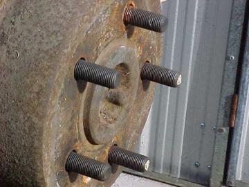
- It is advisable to fit new wheel studs while the axle is disassembled.
- Appropriate studs were available from Ford at reasonable cost.
- They are about 6mm longer which compensates for the thickness of the brake disc and allows for full engagement of the wheel nuts.
- When fitting the new wheel bearing you will also need to fit a thicker axle seal as used on the Ford.
- The outer bearing retainer presses on the seal which then presses on the bearing keeping it in place.
- The centre of the brake disc must be machined to enlarge the hole to accommodate the protrusion on the axle flange.
- This protrusion locates the centre of the road wheel and is designed to carry the weight of the vehicle on that wheel. The protrusion should not be machined to match the disc.
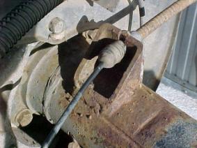
- It will be necessary to fabricate two brackets for the handbrake cables.
- I used a section of heavy gauge square tube which is cut on an angle with appropriate holes and slots. These are then welded to the axle tube.
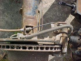
- The brackets need to be mounted close to the end of the axle tube so that the cable does not interfere with the spring in the rear suspension. If the cables are mounted as shown it will be necessary to swap the handbrake mechanism from the right caliper to the left.
- The cable on the Ford runs under the axle tube and pulls the lever in the opposite direction.
- The handbrake cables are the rear sections of the Ford cable with a new ferrule attached at the front to engage the existing Leyland handbrake cables.
- These ferrules were silver soldered (brazed)onto the cable as I was advised that swaging as original could not be satisfactorily performed outside the factory.
- The original handbrake linkage does not provide enough travel to engage and release the Ford handbrake mechanisms.
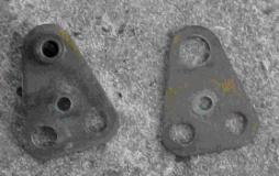
- Additional travel was achieved by modifying the triangular pivot mounted under the handbrake lever on the right hand sill.
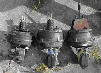
- The link on the right in the above picture is attached to an axle. Cutting off the link in a lathe can salvage the
- 'axle'. It can then be used with the new links.
- Two of the modified handbrake linkages should be cut from 1/8 steel plate. The short rod which runs from this link to
- the plastic quadrant (which the handbrake cable runs around) must be shorter still by 25mm.
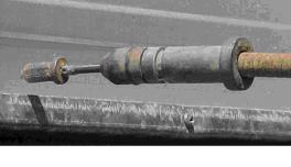
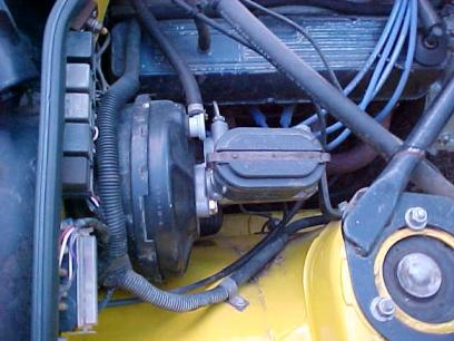
- The brake master cylinder was replaced with a Commodore unit. This incorporates a proportioning valve suitable for use with rear disc brakes.
- The brake booster was also changed to match. Both these items came from VK model Commodore and were the same 1 bore as the original Leyland master cylinder. A 15/16 version is also available but this will increase hydraulic line pressure which may cause brake lockup.
- The Commodore booster will bolt directly onto the Leylands firewall. The pushrod which connects to the brake pedal must be modified.
- The standard booster/master cylinder is shown on the left in the above picture. The unmodified Commodore unit is on the right. The modified one is in the middle. In my application , I cut the pushrod to length and then cut a thread into it to attach the clevis and make it adjustable.
- It may be possible to have a Leyland pushrod fitted to the Commodore booster by a brake specialist.
- New brake pipes will be required to connect to the master cylinder. New brake pipes are also required to run across the diff housing from the flexible hoses on the calipers to the T-piece in the middle.
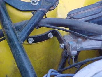
- A further modification is to place a bracket on the front of the master cylinder to secure it to the strut tower.
- This will stop the firewall flexing when the brake pedal is pressed heavily. A similar bracket is fitted to Commodores.
This site is hosted on
Freeservers Reliable, Free Web Hosting |
Last updated Feb, 2006 |
This web site may contain Copyright material If you find any problems with the site, please email the Web Editor  |